Now that you have completed the first part of your traffic impact analysis, let’s take a look at the next step. First, we will create a foundation for your trip distribution and assignment that will provide you with more insight for your project.
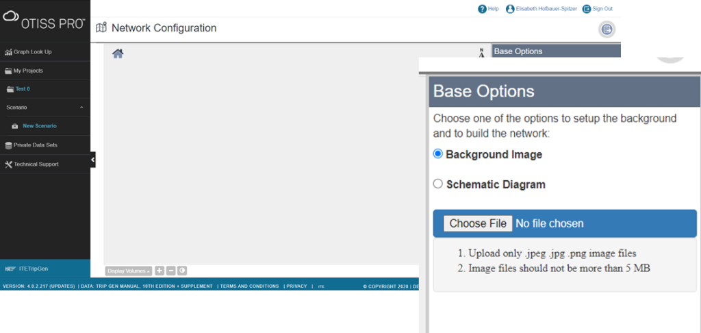
- To start the “Network Configuration” component, click on a scenario and select the Network Configuration.

Build Study Site Road Network
- Upload a background as your baseline for your road network. Two options are available: Background image or schematic Diagram (jpeg, jpg or png).
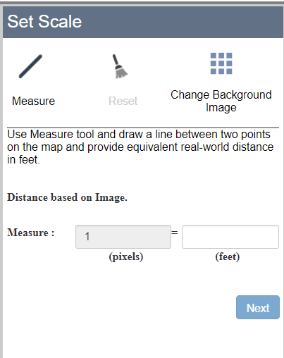
- After the chosen file is uploaded, a Set Scale option is available. To set the scale follow the prompt menu.
- Set the North direction for the drawing canvas by clicking within the compass circle, moving the arrow to the desired direction, and then clicking to the end. Click Next to continue.
Note: Setting the North direction Helps OTISS Pro understand and ensure the reports capture the direction of traffic correctly (e.g. Northbound, Southbound, etc).

Your baseline is now setup – you can draw your network system following the next steps.
Network and Data Module Overview
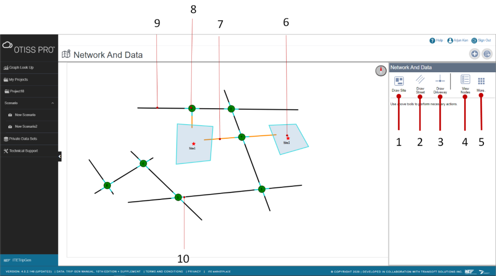
- Draw Site – draw one or multiple sites by defining a shape (e.g. polygon)
- Draw Street – draw a street by defining 2 points, intersecting points of 2 streets will create a Node
- Draw Driveway – draw a driveway by defining a point within a Site to an adjacent Street or a Node with 3-legs (i.e. T-intersection)
- View Nodes – view a list of Nodes (i.e. intersections)
- More – access additional functions e.g. delete the network drawn or to start over
- Study Site
- Driveway
- Node (Intersection or Driveway Intersection)
- Street
- Intersection Leg
- Use the Draw Site tool to draw a closed polygon on the drawing canvas to represent a site. Once a site is drawn, select the Land Uses to assign to the site (hold Ctrl to select multiple land uses).

- If there is more than one study site, you can continue to use Draw Site to create additional polygons and assign land uses to them.
- Use the Draw Street tool to draw streets around the site. Left-click to start drawing the street and repeat again to define point A-B. Right-click to end the command.
Note: Nodes are automatically created when streets intersect.
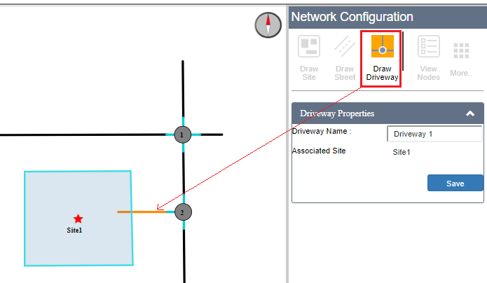
Use the Draw Driveway tool to draw a driveway from the study site to the street (or node). Left-click within the site polygon and left-click on the adjacent street or existing Node.
- Once Streets and Nodes are defined, you can click on any of the intersection nodes to enter more details at the intersection. Alternatively, you can click View Nodes to see the list of nodes and pick the desired node to Edit Intersection Details.

- In the Edit Intersection Details dialog box, refer to the circle diagram to see the highlighted intersection leg to provide Approach and Intersection data. Approach data captures the details for 1 leg of the intersection.
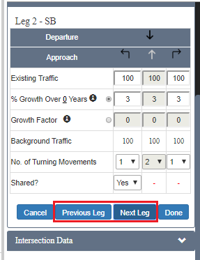
- Click Next Leg or Previous Leg to navigate to the other legs
- To define the permitted traffic movements, click on the turning direction arrows to enable or disable the turning direction (by default, everything is enabled). Using these controls, you can define one-way outbound by disabling all the Approach turning direction arrows and enabling the Departure arrow.
Note: The grey colored arrows are shown when disabled.

- Specify the Existing Traffic for each turning direction if applicable.

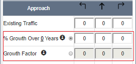
- To define Growth Over X Years, click the 0n the label to enter the number of years to project traffic. This sets the horizon year for the scenario to calculate the Background Traffic. Enter the growth %.

- (Optional) To define growth as a factor instead of using % and year, select Growth Factor and specify appropriate values to estimate the Background Traffic.
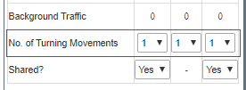
- Specify the Number of Turning Movements (including shared lanes) for each turning direction.
Note: This is not required for the analysis done in OTISS Pro but will be useful if you wish to export data to Synchro.
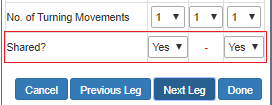
- If any of the left turning movements are shared with the through movements, set Shared to Yes; otherwise, leave it as No. Do the same for the right turning movements.

- Specify a name for the intersection.

- Specify the type of intersection. By default, the Intersection Type is set to Signalized.
Note: This is not required for the analysis done in OTISS Pro but will be useful if you wish to export data (e.g. the corresponding intersection type) to Synchro.

- Click the Done button once the data entry is completed.
- Click Next Leg or Previous Leg to navigate to the other legs
- (Optional) In case you decide to draw the network again, click the Start Over button or Delete the Network, you can find these functions under More.

You have now completed the definition of the site, streets and intersection data. Proceed to the next analysis module: “Driveway Distribution“.